「OpenCV tips ②【C++でArUcoマーカの生成・検出を行う】」でArUcoマーカの生成と検出を行いました。
本記事では、カメラで検出したマーカまでの位置を推定し、ROSのRvizに表示してみました。
使用した環境
・ Ubuntu 20.04
・ OpenCV 4.2.0
・ Cmake 3.16.3
・ ROS noetic
必要なパッケージのインストール
以下のコマンドを実行し、必要なパッケージをインストールします。
sudo apt install -y ros-noetic-desktop-full python3-rosdep python3-rosinstall python3-rosinstall-generator python3-wstool build-essential python3-osrf-pycommon python3-catkin-tools
以下のコマンドを実行し、環境設定を行います。
echo "source /opt/ros/noetic/setup.bash" >> ~/.bashrc
source ~/.bashrc
sudo rosdep init
rosdepp update
aruco_markerパッケージのダウンロード・ビルド
「aruco_marker.zip」
以下のコマンドを実行し、aruco_markerパッケージを指定の場所に配置します。「aruco_marker.zip」は上記リンクからダウンロードしてください。
cd ~/ダウンロード
unzip aruco_marker.zip
mkdir -p ~/catkin_ws/src
cd ~/catkin_ws/src
cp -rfp ~/ダウンロード/aruco_marker .
cd ~/catkin_ws
catkin build
source devel/setup.bash
ArUcoマーカの位置推定プログラムの実行方法
1つ目のターミナルを起動し、roscoreコマンドを実行します。
roscore
2つ目のターミナルを起動し、ArUcoマーカの位置推定プログラムを実行します。
rosrun aruco_marker arMarkerCoordEstimator_node
3つ目のターミナルを起動し、Rvizを起動します。Rvizの「Displays」パネル→「Add」→「By topic」タブ→「/camera/image_raw」トピック→「Image」を追加し、カメラ画像を表示します。
rosrun rviz rviz
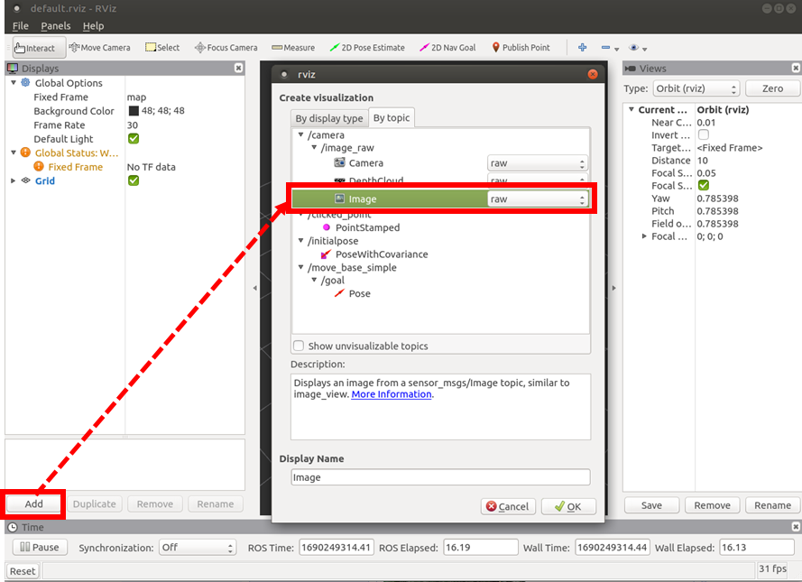
Rvizの/image_rawトピック追加手順
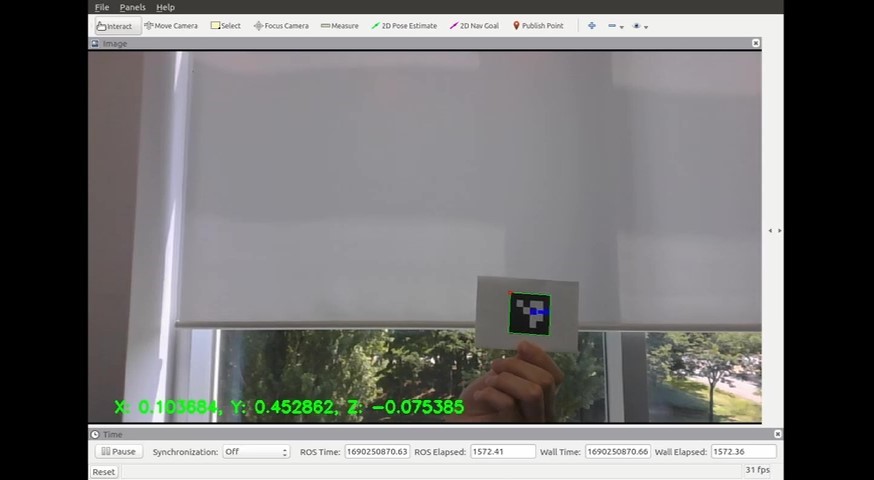
Rvizに表示したカメラ画像
ArUcoマーカの位置推定プログラムの説明
73~89行目でArUcoマーカの四つ角の座標から画像上のマーカの大きさ(ピクセル数)を求め、91~92行目でマーカの四つ角の座標とマーカの大きさから画像上のマーカの中心座標を求めています。
aruco_dis_x = maxCornerCoodinate(coners[i][0].x, coners[i][1].x, coners[i][2].x, coners[i][3].x, corner_id);
if(corner_id == 0){
	aruco_dis_x = std::max(aruco_dis_x - corners[i][3].x, aruco_dis_x - corners[i][corner_id + 1].x);
} else if(corner_id == 3){
	aruco_dis_x = std::max(aruco_dis_x - corners[i][0].x, aruco_dis_x - corners[i][corner_id - 1].x);
} else {
	aruco_dis_x = std::max(aruco_dis_x - corners[i][corner_id - 1].x, aruco_dis_x - corners[i][corner_id + 1].x);
}

aruco_dis_y = maxCornerCoordinate(corners[i][0].y, corners[i][1].y, corners[i][2].y, corners[i][3].y, corner_id);
if(corner_id == 0){
	aruco_dis_y = std::max(aruco_dis_y - corners[i][3].y, aruco_dis_y - corners[i][corner_id + 1].y);
} else if(corner_id == 3){
	aruco_dis_y = std::max(aruco_dis_y - corners[i][0].y, aruco_dis_y - corners[i][corner_id - 1].y);
} else {
	aruco_dis_y = std::max(aruco_dis_y - corners[i][corner_id - 1].y, aruco_dis_y - corners[i][corner_id + 1].y);
}

	image_dis_x = std::min({corners[0][0].x, corners[0][1].x, corners[0][2].x, corners[0][3].x}) + aruco_dis_x / 2.0;
	image_dis_y = std::min({corners[0][0].y, corners[0][1].y, corners[0][2].y, corners[0][3].y}) + aruco_dis_y / 2.0;
160~168行目で画像座標系からカメラ座標系に変換しており、光学中心と焦点距離からカメラ座標ベクトルを求めています。
Eigen::Vector3f convertImageToCameraCoordinates(const bool debug=false)
{
	Eigen::Vector3f v_;
	v_.x() = (image_dis_x - h_size / 2) / focalLengthMmToPixels(h_dis, h_size, mode);
	v_.y() = (image_dis_y - v_size / 2) / focalLengthMmToPixels(v_dis, v_size, mode);
	v_.z() = 1.0;

	return v_;
}
ここで、カメラのイメージセンサから求めた焦点距離の単位は[mm]なので、134~142行目で単位を[mm]から[pixel]に変換しています。
float focalLengthMmToPixels(float dis, int size, const bool debug=false)
{
	float pixel_;
	float diagonal_dis;
	diagonal_dis = imageSensorDiagonalDistance(h_dis, v_dis);
	pixel_ = size / dis * focalLength(diagonal_dis, fov, mode);

	return pixel_;
}
173~198行目でカメラ座標系からワールド座標系に変換して、推定座標をカメラ画像上に表示しています。177行目の変数tでカメラ座標系の原点をワールド座標系の原点と一致するように移動させ、179行目の変数Rinvでカメラ座標系の各座標軸をワールド座標系と一致するように回転させます。191、193行目でカメラ座標ベクトル、実物のサイズ(今回使用したマーカは4cm×4cm)、画像上のマーカサイズ(ピクセル数)からカメラ座標系でのX(横方向)、Z(縦方向)座標を求めており、192行目で実物のサイズ、イメージセンサに写った対象物の大きさ、焦点距離から奥行きの推定を行っています。
Eigen::Vector3f convertCameraToWorldCoordinates(const bool debug=false)
{
	Eigen::Vector3f v_, v_camera, t, tmp;
	Eigen::Matrix3f R, Rinv;
	t << 0, 0, 0;
	R << 1, 0, 0, 0, 1, 0, 0, 0, 1;
	Rinv = R.inverse();
	tmp = convertImageToCameraCoordinates(mode);
	float marker_size = 0.04;
	// Focal length d'.
	float dd = focalLengthMmToPixels(v_dis, v_size, mode);
	// The size of the subject reflected on the image sensor.
	float hd = aruco_dis_y;
	// Distance to the subject.
	float d;
	// Size of the subject is 0.04[m](4.0[cm]).
	float h = 0.04;

	v_camera.x() = -tmp.x() * (h_size / 2.0 - image_dis_x) * (marker_size / aruco_dis_x) / tmp.x();
	v_camera.y() = (tmp.z() * h * dd) / hd;
	v_camera.z() = tmp.y() * (v_size / 2.0 - image_dis_y) * (marker_size / aruco_dis_y) / tmp.y();
	v_ = Rinv * (v_camera - t);

	return v_;
}
座標系の変換等については、以下のページをご参照ください。
【参考】
・カメラパラメータ・座標変換 https://qiita.com/S-Kaito/items/ace10e742227fd63bd4c
・画像座標系からカメラ座標系への変換 https://mem-archive.com/2018/10/13/post-682/
・焦点距離の単位[mm]から[pixel]の変換 https://mem-archive.com/2018/02/25/post-201/
・カメラ座標系から世界座標系への変換 https://mem-archive.com/2018/10/28/post-962/
・画像や写真に写る物体までの距離推定と精度検証 Python https://miyashinblog.com/distance-estimation/
いかがだったでしょうか。
以前行ったArUcoマーカの検出と組み合わせてマーカの座標位置を推定してみました。
皆様が使用する際は、ArUcoマーカのサイズ、カメラの焦点距離、カメラの向きなどを実際の値に変更して使用してください。